Forced induction is a huge key to making power in a diesel engine. It is one of the biggest advantages that a diesel has over a gasoline engine. When it comes to air management a diesel engine can run a wide range of air to fuel ratios and still function correctly. Some of the biggest competition trucks will run air/fuel ratios way south of 15:1. On the other side of the coin, while coasting downhill many of today’s engines don’t even inject fuel into the engine. For example: in our How It Works Water Methanol, we calculated stoichiometric air/fuel ratios of pump diesel to be anywhere from 15.5:1 to 23:1 with the average fuel at the pump being around 17.75:1.
With that being said, everything has to be designed and built to handle large amounts of air and boost pressure. Luckily, for most of us who drive trucks that are 20 years old or newer, our engines are already designed for some boost pressure. The question becomes, how much can the engine ultimately take before additional modifications are needed? Of course, this varies by manufacturer and the specific engine design.

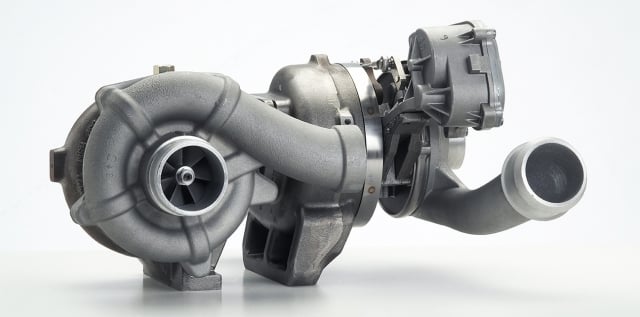
The 6.4 Power Stroke engines use a sequential turbocharger to provide excellent low-end spool up while not sacrificing mid- or top-end performance. Photo courtesy of BorgWarner.
So, when adding a turbocharger that produces more boost pressure than the engine was originally designed for, many people will want to regulate the boost down to a certain point. So, how do you regulate something that spins as a result of heat and pressure? Turbochargers are exhaust driven (drive pressure), so people regulate the boost pressure with what’s known today as the wastegate.
What Exactly Is A Wastegate?
A wastegate is a valve that allows a certain amount of exhaust flow to bypass the turbine wheel. This reduction in flow, results in a reduction of drive/back pressure. There are many factors that can contribute to the overall performance of a turbocharger which are beyond the scope of this particular article. To keep things simple, let’s assume that as the drive pressure increases, the turbine wheel will spin faster.

Garrett recently introduced an entirely new design with their single sequential turbochargers. These compressor wheels feature two profiles. One side is a small compressor wheel for low-end performance and the other side is a larger wheel for mid- to high-end performance.
As an engine’s RPM increases and more fuel is being injected into the engine, there is more and more exhaust flow. As this flow increases, it eventually is greater than what the turbine housing can flow through the turbine wheel at atmospheric pressure and the flow starts to back up. The back up in the flow increases exhaust pressure (drive pressure). As the drive pressure increases, the turbine wheel spins faster. Since the turbine wheel is directly connected to the compressor wheel, the compressor wheel spins faster and faster, creating more and more boost.
In theory, this could be a never ending cycle but, in reality, any given turbocharger setup has its design limitations. So, there is a maximum amount of boost most chargers will produce, which is usually between 30 and 50 psi on our engine applications. If the engine isn’t designed for that amount of pressure, a wastegate needs to be added to divert a certain amount of the flow. By reducing the flow through the turbine wheel, the actual amount of drive pressure can be regulated. There are two different types of regulators that are used; internal and external.
Internal Wastegates
An internal wastegate refers to a wastegate that is designed into the turbine housing. These gates generally have one or two pucks (a round piece of metal that acts like a valve) that block passages that are drilled or cast into the scroll of the turbine housing. When the pucks are closed, the exhaust flows around the scroll (the passage inside of the turbine housing) and through the turbine wheel like a non-wastegated unit. When the pucks are moved (or open), some exhaust will flow through the scroll and some will bypass the scroll and turbine wheel. In an internal wastegated turbine housing, the bypassed exhaust is directed back into the main exhaust stream after the turbine wheel, but usually before or right at the down pipe. These are self-contained units that typically don’t require any additional plumbing.
The amount of exhaust that can bypass the turbine wheel is dependent on the size and design of the wastegate area. Since most wastegated turbine housings are designed for original equipment (OE) diesel engines, these housings usually feature fairly small passages that don’t flow a whole lot of volume. The reason is because at high pressure, it doesn’t take much of an opening to bleed pressure off. These work great if the engine isn’t producing a lot more volume than the turbine housing can handle (more on this later).
 There are two popular methods to control the wastegate. The first method, which is tried and true, is to use a boost operated canister (referred to as a “can”). These Cans are designed to work at a certain boost range, say 10 to 20 psi. There are only a few parts to a traditional Can.
A: Diaphragm – The diaphragm has a seal that keeps the boost pressure from escaping.
B: Spring – With a Can, the spring is actually providing the force to keep the wastegate shut.
C: Actuator Rod – A rod that connects the wastegate actuator arm to the diaphragm.
Depending on how much the spring has been compressed, will depend on the actual amount of boost pressure needed to overcome the spring. Once the force generated by the boost exceeds the force generated by the spring, the spring starts to contract, moving the actuator rod and opening the gate. (Almost the reverse of a BOV discussed here.) So, the actuation of the wastegate is based on the boost being sent to the Can. In the past, the biggest issues with a Can is the limited range of options.
Most are rated for 10 to 20 psi but in the aftermarket, we run much higher pressures. Turbosmart, just recently, introduced their new IWG HP. These wastegate actuators come in a variety of boost pressures ranging from 10 psi to 40 psi. “Turbosmart’s Internal Wastegate actuators are great in many diesel applications,” says Marty Staggs, Executive Vice President/General Manager Turbosmart USA. “Not only are they a cost-effective performance upgrade, but a well designed wastegate actuator like these, truly have the ability to bolt right onto your stock turbo, making it a very simple install. Since the diesel performance market has much higher boost levels for their norm, we’ve engineered our IWG lineup with the diesel market specifically in mind, and their ability to handle high boost is unparalleled,” shared Staggs.
The second and fairly recent way to control the wastegate is by using a spring regulator (drive pressure regulator). Many aftermarket companies use spring controlled actuators but OEM turbochargers don’t currently use this method. These drive pressure regulators have a spring under constant compression. The force the spring produces is the force holding the wastegate shut. To actuate the wastegate, the drive pressure from the engine is used. As the drive pressure increases, it pushes up on the pucks. Once the force of the drive pressure exceeds the spring pressure, the wastegate starts to open. This type of regulator regulates the boost by regulating the drive pressure (discussed further below).
External Wastegate
The next type of wastegate is an external wastegate. External wastegates are completely separate from the turbine housing. In fact, they are a stand-alone part that can be added to any type of turbocharger system. The gates themselves have a few moving parts and are a pretty basic assembly.
 A: Inlet Flange – The lower part is the inlet flange. The inlet flange is usually welded to the up-pipes. To flow the best, the exhaust should flow as smoothly as possibly into the gate and not against the normal flow of the gas.
B: Bushing – The bushing is needed so manufacturers can install the valve into the wastegate and have it seal against something. The bushing rides inside of the main body of the wastegate.
C: Main Body – The bodies are almost always cast parts that are designed for specific temperature ranges. The higher temperature the exhaust reaches, the more heat tolerant the material needs to be. This is why you will see gates made out of stainless steel and Inconel as both of these materials have good thermal properties. The bodies are usually connected to the inlet flange by a v-band clamp.
D: Valve – Inside of the body is the valve. The valve is responsible for keeping the exhaust gasses out of the gate when it is closed. The design of the wastegate body and valve determine the flow characteristics. Most gates are designed to flow a low amount when they are initially opened, but then as much as possible when fully opened. If the gate flows too much, it can actually drop the drive pressure to such a degree that the charger can lose all of its boost. So, gates are offered in different sizes, usually ranging from 40mm to 60mm. This makes choosing the right size for the specific application a very important step.
E: Actuator Body – Above the main body of the wastegate is the actuator area. To minimize heat soak (thermal heat transfer from the main body into the actuator area) this is usually spaced above the physical body with spacers. Inside of the actuator there is a piston (E.1) that is directly connected to the valve. The piston will have a seal (E.2) to create an air-tight area above the piston. These seals won’t last at high exhaust gas temperatures (EGT’s), which is generally why there are spacers between the body and the actuator area. On top of the piston is the spring (E.3). This spring helps to return the valve back to the seated position as quickly as needed. In this area, there is also a port for boost pressure to be supplied on top of the piston to control the opening of the valve.
For a wastegate to operate, the forces acting on the actuator piston need to be dynamic (change with time). While there is a constant force being applied by the spring (Fs) the force being applied is relatively low. As such, the force being applied by the drive pressure (Fd) would start opening the wastegate pretty early. To keep the gate shut longer, there is boost pressure supplied to the top of the actuator piston. This pressure multiplied by the area of the piston creates the opposing force to keep the gate shut (Fb).
For tunability, an air pressure regulator or boost controller is generally plumbed in line with the supplied boost pressure. So, as long as Fd is less than Fs + Fb the gate will stay shut. When regulating the gate, the installer can pretty much get the gate to open from relatively low boost by supplying no boost pressure (Fd just needs to be greater than Fs), to having the gate only open at high boost pressure (once Fd is greater than Fb + Fs). This makes external regulators extremely tunable.
If the end user was only worried about regulating the boost pressure, then this article would be complete. But there is an additional reason to add a wastegate to your system. As mentioned above, diesel engines operate with wide ranges of air/fuel ratios. So, many systems are designed to provide boost at relatively low RPMs. In order to achieve that, many turbocharger kits use turbine housings that are a little small for the top-end horsepower, but offer quicker spool up. The charger will usually reach maximum boost pressure, but with a slight downside. The smaller turbine housing can cause an excessive amount of drive pressure. The higher the drive pressure the more exhaust that remains in the cylinder, which means less oxygen to burn. In addition to having less oxygen available for combustion (i.e. less power), the exhaust that remains in the cylinder heats up the cylinder air and exhaust gas temperatures (EGT) can start to spike. So, if maximum boost is desired, but we want to minimize drive pressure, the wastegate needs to open only after maximum boost has been reached.
Well, that begs the question – how do you open a wastegate after maximum boost pressure has been achieved if you regulate a gate by boost pressure?
Final Options
For an internal wastegated housing this can be difficult. A Can is usually designed to operate at moderate boost levels. One way installers get more boost pressure (or delay opening the gate) is by putting more tension on the actuator rod. To achieve this, the rods are usually shortened (either by physically cutting them down or by threading them down) which puts more strain on the internals of the regulator, but it does make the gate stay open later. Another option is a spring operated regulator. These can be adjusted so that only after maximum boost pressure has been achieved, will the gate open. The major concern with this much force opposing the drive force is when the drive force is removed (when you let off the throttle) the actuator closes the gate pretty hard. After some time, many internals start to bend and the wastegates could start to leak.
For an external wastegate, regulating based on drive pressure can also be difficult. Due to the o-rings inside of the gate, you can’t send hot exhaust gasses directly to the top of the actuator. In addition, the actuators aren’t designed for soot. In order to use drive pressure to open a gate, it must be sent through a cooler (usually a coil of cooper tubing) and then into a filter. This will provide filtered exhaust (i.e. no soot) at a lower temperature. From there, the drive pressure can be sent into a regulator and then to the actuator. This way requires a lot more plumbing, but this will effectively allow tuning of the wastegate based off drive pressure. Many sled pullers who prefer a lot more drive pressure than boost pressure to help prevent the charger from “woofing out” at the end of the track, will run this type of setup. What they do is open the gate with 10 to 20 psi higher drive pressure than maximum boost pressure.
Companies like Turbonetics with their Torque-Master wastegates have a slightly different approach. They still operate the wastegate like normal (with boost), but use a much stiffer spring and larger actuator piston to keep the gate shut. “Guys competing shouldn’t have to worry about filters clogging up or burning up a seal at the track. We took what we have learned through our OEM business and with our competition vehicles to design a monster of a wastegate,” says Reggie Wynn, Inside Sales Manager at Turbonetics. “This gate is designed for high boost applications. All of the parts are much larger and more durable than a standard gate. As a result, the increased size makes fine tuning the gate easier,” continued Wynn. Thanks to the increased size of the actuator there is more force keeping the gate shut (Fb) at the same boost pressure than a standard external wastegate. This means that sled pullers can use boost pressure to regulate the wastegate and sill achieve a decent amount of drive pressure above the boost pressure to stay on top of the turbo.”
So there you have it – Wastegates explained. Stay tuned as we dive deeper into the ins and outs of Diesel Performance, right here on Diesel Army!


